FORT STANWIX
History, Historic Furnishing, and Historic Structure Reports
|

|
Historic Structure Report
ILLUSTRATIONS
|
|
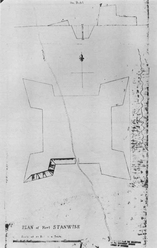
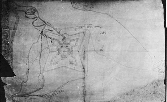
"PLAN of Fort STANWISE," possibly drawn by James Montresor,
engineer, in 1758. If this drawing in the Montresor plan, it is our first scaled and dimensioned document of
Fort Stanwix. The lengths of the flanks and faces as well as the overall distance between the salient angles
of the bastion tips, as shown on this plan, compare very favorably with the proposed reconstruction
dimensions. Reproduced from the Collections of the Manuscript Division, Library of Congress.
|
|
|
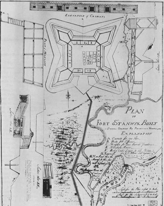
"PLAN OF FORT STANWIX BUILT at ONEIDA STATION by PROVINCIAL
TROOPs in 1758" signed by Jn. Williams, Fort Stanwix as it looked after the initial round of construction by the colonial
troops supervised by regular British and Provincial Army officers. Construction details for the ramparts and casemate walls
as well as for the footbridge and necessary structure were taken from this plan. Reproduced from the Collections of the
Manuscript Division, Library of Congress.
|
|
|
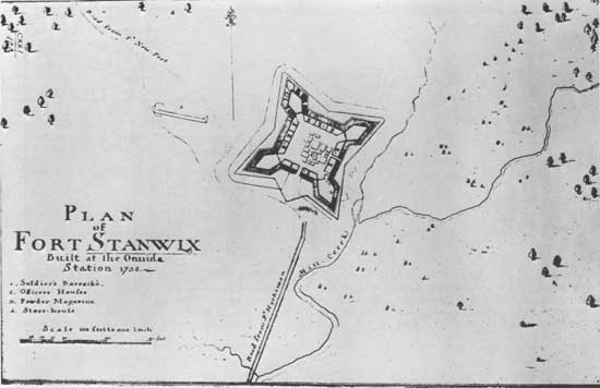
"PLAN OF FORT STANWIX, Built at the Onnida [sic] Station 1758." This
plan was probably drawn in 1759 or 1760 since it sows the two additional buildings on the parade ground constructed
"from July to December 1759." Note the storehouse to the northwest, built outside the fort. Reproduced from the
Collections of the Manuscript Division, Library of Congress.
|
|
|
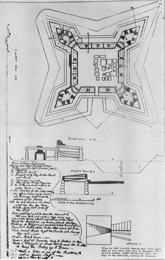
"Plan of FORT STANWIX showing what Works were done at that
Post—from July to December 1759." The original plans at the British
Museum, were colored to show the extent of new work as listed in the
explanation at the lower left of the drawing. The National Park Service
should obtain color reproductions of these original drawings to complete
this part of the fort story. This is one of two plans that show the
location of the fraise; see "Profill thro A B." It also shows the
earliest type of construction of the parapet in "Profill throu E F."
Reproduced from the Collections of the Manuscript Division, Library of
Congress.
|
|
|
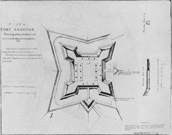
"Plan of FORT STANWIX, Showing what is to be done to compleat it." Dated
(in another script) 1764. Unsigned. A black and white copy of another
original colored plan kept in the British Museum. Compare this plan with
the previous ones to see the changes that were made to the buildings on
the parade ground. A new covered communication (caponière) was added to
the east end of the sally port and a newly built ravelin constructed
opposite the main gates and bridge. This plan furnished the primary
construction details above ground level for the sally port and redoubt
beyond. (See sections A B and C D.) Reproduced from the Collections of
the Manuscript Division, Library of Congress.
|
|
|
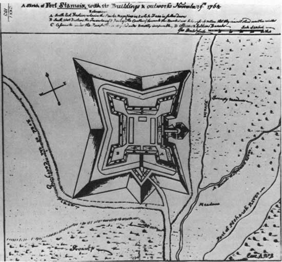
"A Sketch of Fort Stanwix, with its Buildings & outworks
November 19th 1764" signed by Geo. Demler. This and the previous plan
are the only two drawings found to date that indicate the work done by
the British at For Stanwix "between the 1st of July 1764, and 31st of
December followg." This plan was used to locate the placement of the
picket line along the east berm of the fort. Also, the method of closing
off the northeast and southeast ends of the ditch as shown on this plan
was adapted in the proposed preliminary plans. Reproduced from the
Collections of the Manuscript Division, Library of Congress.
|
|
|
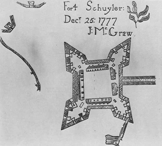
"Fort Schuyler: Decr 25: 1777, J: Mc Graw." A two dimensional drawing of
the original McGraw powder horn now owned by Chester Williams of Rome,
New York. Drawing by John McManagle of Rome, New York, in 1963. James
(Alexander) McGraw enlisted in the American army during July of 1775. He
participated in the invasion of Canada in 1776 where he was shot through
the leg. On June 13, 1777, McGraw reenlisted in Capt. Bleecker's Company
of the 3rd New York Regiment, which arrived at Fort Stanwix on May 26,
1777. Although we are not positive that James McGraw was here at the
fort during the siege, it seems very likely that he was. Our first
account of McGraw actually being at the fort is found in a hospital
return dated March 1, 1778, which lists (James) McGraw, Capt. Bleecker's
Company, as having been confined to his quarters with an "Ulcerous leg."
This was surely the old leg wound of 1776 acting up again. During
McGraw's period of convalescence, he would have had time to carve the
fort plan on his powder horn. McGraw was discharged on May 30, 1778, "as
unfit for duty from his wound and old age." Source: Original sketch at
Fort Stanwix Museum, Rome, New York.
|
|
|
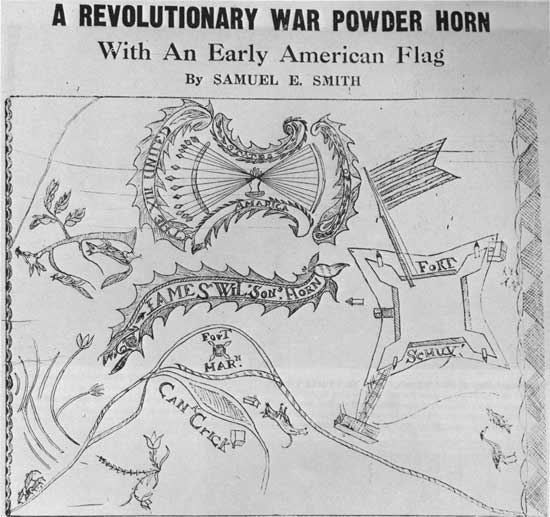
The James Wilson powder horn of Fort Schuyler. James Wilson was a
private in the 1st Company of the 1st New York Regiment commanded by
Col. Goose Van Schaick. The 1st New York Regiment replaced the 4th New
York Regiment at Fort Stanwix near the end of 1778. The regiment stayed
at the fort until November of 1780; thus, the Wilson powder horn has a
probable date of 1779 or 1780. The Wilson powder horn is unique in that
it shows the location of five sentry boxes, four of them found on the
bastions. The structure shown on the southeast bastion is surely the
shed that "the Carpenters are to pull down ...Built Over the bomb
proof." (Garrison order, Dec. 20, 1780.)
|
|
|
"Gansevoort Map of Fort Stanwix." New York Public Library.
|
|
|
Plan of Fort Stanwix dated 1802. The original drawing of this plan has
not been located to date. Presumably it was drawn on its spot by the
Rev. John Taylor, but not published until 1850. Rev, Taylor writes in
his journal on ihe 18th: "The old Fort Stanwix stands about 30 rods
from ye river. It is regularly built: the intrenchments is very deep. In
the centre of the fort stands the old block house. This can better be
described by my drawing." Another eyewitness report of 1815 placing the
blockhouse of 1794 in the center of the old Fort is solid evidence that
this was the location of its construction, Source: Documentary
History of New York, Vol. III, 1850, p. 1137. (Jervis Library, Rome,
N.Y.)
|
|
|
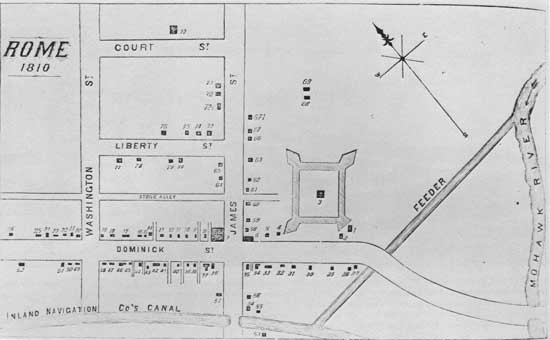
Plan of Fort Stanwix, dated 1810. The original drawing of this plan has
not been located as yet. It first appeared in a local newspaper, the
Rome Citizen in 1871. Later, in 1878, it was published in book
form. The description, in part, of Fort Stanwix reads as follows: "Fort
Stanwix originally extended through from Dominick Street to what is now
Liberty Street, and the block-house was in the centre (about where Dr.
Kingley's barn is)." The plan shows that the leveling of the Fort proper
started in the southeast bastion where Mr. Dominick Lynch built a house
between 1802 and 1810. Source: History of Onieda County, New
York, by Samuel W. Durant, 1878, p. 382. (Jervis Library, Rome,
N.Y.)
|
|
|
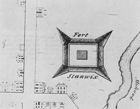
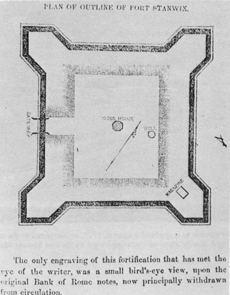
Plan of Fort Stanwix as engraved upon an original Bank of Rome note in
1832. An octagonal blockhouse, a well and magazine are shown on the
plan. The fort and the blockhouse were probably gone prior to 1832;
thus, the engraving probably represents the fort as someone remembered
it, Source: From the Rome Directory of 1857, p. 131. (Jervis
Library, Rome, N.Y.)
|
|
|
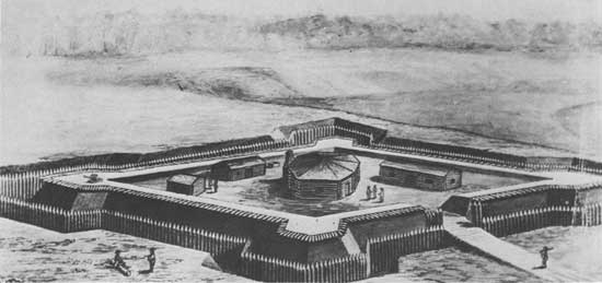
Drawing of Fort Stanwix, dated 1793, attributed to Peter Hugunine.
Actually misdated, as the blockhouse was not constructed until 1794.
This sketch represents the artist's conception of Fort Stanwix in 1793.
We have very little information on the blockhouse of 1794. In 1815,
William Dunlap made a drawing of the remains of Fort Stanwix, showing
the blockhouse that occupied the "centre of the fortification." An
unsuccessful attempt was made to locate the drawing, which may have
perished in the Dominick Lynch house fire of c. 1824. Source: From a 4"
x 7" negative owned by Chester Williams, Rome, New York.
|
|
|
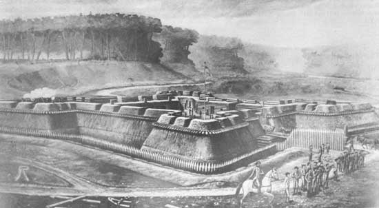
Fort Stanwix as it appeared August 6, 1777, as interpreted by the
artist, Peter Hugunine, in 1897. The original oil painting has not
been located. Source: From an engraving owned by the Fort Stanwix Museum,
Rome, New York.
|
|
|
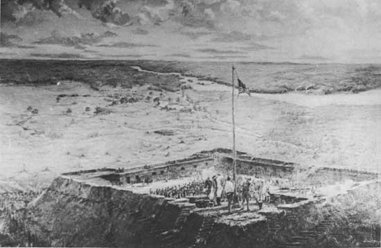
"Sunrise at Fort Stanwix August 3, 1777." An oil painting by Edward F.
Buyck in 1927. Funds to pay Mr. Buyck for this painting were raised by
the citizens of Rome. The theme of the painting is the raising of the
"Stars and Stripes" above Fort Stanwix during the siege of August 2-22.
Both Hugunine and Buyck elected to show the rampart walls as constructed
from earth covered with sod. Source: Copied from an 8" x 10" B & W
photograph owned by Chester Williams, Rome, New York.
|
|
|
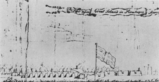
"The Fort upon Great Island in Piscataqua River, 1699, New Hampshire."
This particular sketch has been included to show the location of the
Sentry boxes on the tips of the bastions. A sketch of Fort George, in
the New York Harbor, by Archibald Robertson, dated 1776, also shows a
sentry box placed on the tip of each bastion. This location agrees with
the military handbooks of the day. Crown Map Collection, Mss. Room, New
York State Library, Albany, New York.
|
|
|
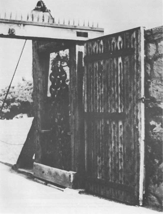
Reconstructed drawbridge and outer gates at Fort Erie, Ontario, Canada.
This is a recent reconstruction, probably within the last ten years. A
similar drawbridge design was used at the Upper Canada Village near
Cornwall, Canada, From a 35 mm. slide taken by O. W. Carroll, 1971.
|
|
|
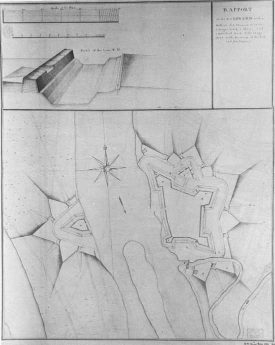
Plan of Fort Edward, New York, c. 1757. The profile drawing through T-U,
showing the exterior construction of the rampart wall and an embrasure,
is the method of construction proposed for Fort Stanwix. Note the
dovetail joints at the corner of the embrasure and rampart end wall.
Along the superior slope can be seen the tie beams, dovetailed into the
inner and outer log walls Library of Congress, No. 45215, January 1973
|
|
|
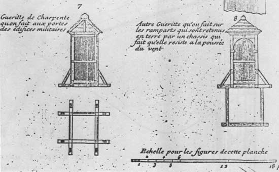
A drawing of a French designed sentry box, dated 1739. We are indebted
to Mr. John Fortier, Head Research Historian at Fortress of Louisbourg
NHP, Canada, for providing us with a copy of this sketch. Since De
LaMarquisie was the French engineer in charge of building the sentry
boxes at Fort Stanwix in 1777, the writer assumes that he would use a
drawing having a French origin. The sentry boxes proposed for use at
Fort Stanwix follow this design. Source: Fortress of Lonisbourg, Canada,
From La science des ingenieurs dans la conduite des travaux de
fortification et d'architecture civile . . .
|
|
|
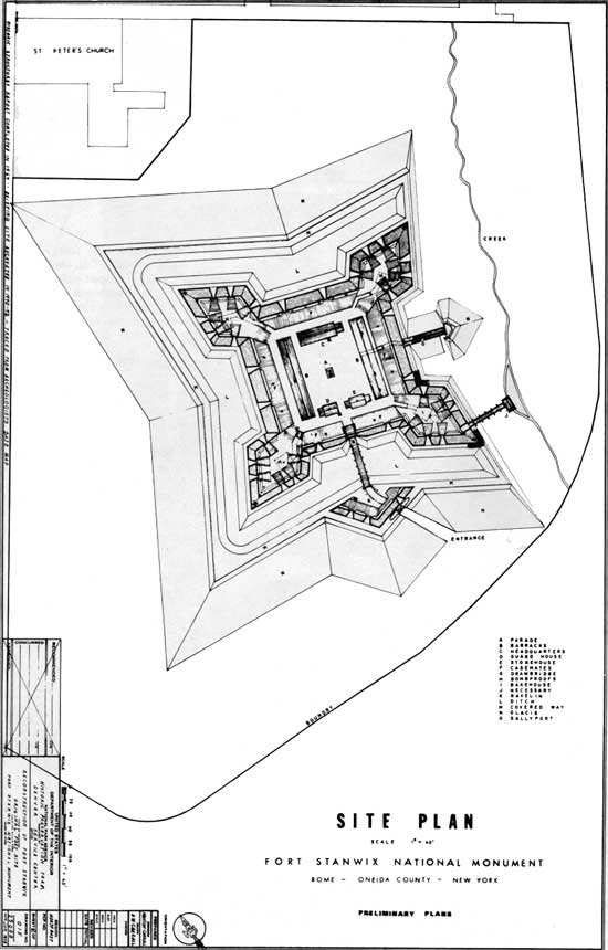
Site Plan, Fort Stanwix National Monument. (click on image for a PDF version)
|
|
|
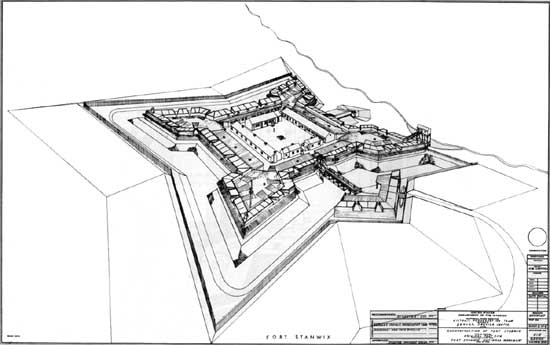
Perspective view of Fort Stanwix, 1776-1781. (click on image for a PDF version)
|
|
|
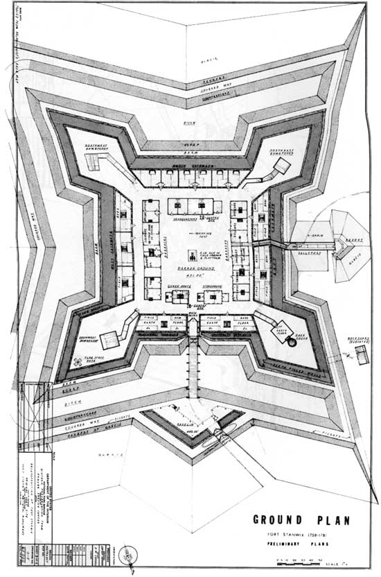
Ground Plan, Fort Stanwix 1758-1781. (click on image for a PDF version)
|
|
|
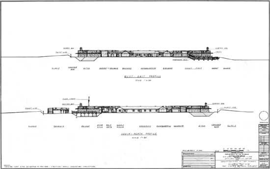
West—East, South—North Profiles. (click on image for a PDF version)
|
fost/history/hsr-illustrations.htm
Last Updated: 26-Dec-2008
|